Parsimony in processing
 | |
| Series | Investigations in Geophysics |
|---|---|
| Author | Öz Yilmaz |
| DOI | http://dx.doi.org/10.1190/1.9781560801580 |
| ISBN | ISBN 978-1-56080-094-1 |
| Store | SEG Online Store |
The primary objective in data processing is to enhance the signal-to-noise ratio while preserving the useful signal bandwidth associated with the recorded data at all stages in the analysis. The principle of parsimony in processing is the basis to achieve this objective. Specifically, a processing sequence should be optimally lean and not include any step that may do more harm than the intended action by that process. A further compelling reason for parsimony is preserving relative amplitudes for amplitude-driven exploration objectives associated with stratigraphic plays.
Figures 1.5-42 through 1.5-53 show the step-by-step appearance of a portion of a stacked section based on a very basic processing sequence intended to minimize amplitude distortions while largely attenuating reverberations, multiples, and random noise and ultimately increasing vertical and lateral resolution.
The stacked sections in Figures 1.5-42 through 1.5-47 were created based on the following prestack processing sequence:
- Figure 1.5-42: stack based on unprocessed data that contain low-frequency swell noise.
- Figure 1.5-43: stack using CMP gathers with low-cut filtering applied to remove the swell noise.
- Figure 1.5-44: stack as in (b) with the additional step for t2 scaling to compensate for wavefront divergence; note the restoration of amplitudes at late times.
- Figure 1.5-45: stack as in (c) with the additional step for prestack spiking deconvolution; note the attenuation of reverberations.
- Figure 1.5-46: stack as in (d) with the additional step for wide bandpass filtering to improve velocity analysis.
- Figure 1.5-47: stack as in (e) with the additional step for dip-moveout correction; note the preservation of diffractions that interfere with the nearly flat reflections.
-
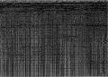 Figure 1.5-42 CMP stack based on recorded data without any prestack and poststack processing.
 -
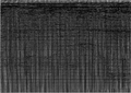 Figure 1.5-43 CMP stack as in figure 1.5-42 based on a processing sequence that includes low-cut filtering of the prestack data, only.
 -
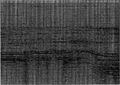 Figure 1.5-44 CMP stack as in Figure 1.5-43 with the additional step in the processing sequence for t2 scaling of the prestack data.
 -
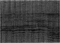 Figure 1.5-45 CMP stack as in Figure 1.5-44 with the additional step in the processing sequence for spiking deconvolution of the prestack data.
 -
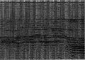 Figure 1.5-46 CMP stack as in Figure 1.5-45 with the additional step in the processing sequence for wide bandpass filtering of the prestack data.
 -
 Figure 1.5-47 CMP stack as in Figure 1.5-46 with the additional step in the processing sequence for dip-moveout correction.


The stacked sections in Figures 1.5-48 through 1.5-53 were created based on the following poststack processing sequence:
- Figure 1.5-48: stack as in (f) of the prestack processing sequence described above with the additional step for poststack spiking deconvolution; note the increase in vertical resolution as a result of wavelet compression.
- Figure 1.5-49: stack as in (a) with the additional step for time-variant spectral whitening to account for nonstationarity.
- Figure 1.5-50: stack as in (b) with the additional step for wide bandpass filtering.
- Figure 1.5-51: stack as in (c) with the additional step for AGC scaling.
- Figure 1.5-52: stack as in (d) with the additional step for attenuation of random noise uncorrelated from trace to trace using f – x deconvolution (linear uncorrelated noise attenuation).
- Figure 1.5-53: migrated stack as in (c) with the additional step for AGC scaling.
-
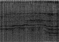 Figure 1.5-48 CMP stack as in Figure 1.5-47 with the additional step in the processing sequence for spiking deconvolution of the poststack data.
 -
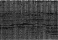 Figure 1.5-49 CMP stack as in Figure 1.5-48 with the additional step in the processing sequence for time-variant spectral whitening of the poststack data.
 -
 Figure 1.5-50 CMP stack as in Figure 1.5-49 with the additional step in the processing sequence for wide bandpass filtering of the poststack data.
 -
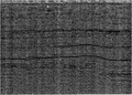 Figure 1.5-51 CMP stack as in Figure 1.5-50 with the additional step in the processing sequence for AGC scaling of the poststack data.
 -
 Figure 1.5-52 CMP stack as in Figure 1.5-51 with the additional step in the processing sequence for f – x deconvolution of the poststack data.
 -
 Figure 1.5-53 Migrated CMP stack as in Figure 1.5-50 with the additional step in the processing sequence for AGC scaling of the Migrated data.


Scan through the stacked sections starting with Figure 1.5-42 and observe the effect of each processing step on the result. Additionally, examine the spectra labeled as (a) through (f) in Figure 1.5-54 which correspond to the stacked sections in Figures 1.5-42 through Figure 1.5-47 involving the prestack sequence, respectively, and the spectra labeled as (a) through (f) in Figure 1.5-55 which correspond to the stacked sections in Figures 1.5-48 through Figure 1.5-53 involving the poststack sequence, respectively. Observe the change in the spectral content induced by each process, and note that the ultimate objectives in processing are aimed at preserving the bandwidth of the recorded signal and flattening the spectrum within the signal passband to attain the maximum possible vertical and lateral resolutions.
-
 Figure 1.5-54 Spectral analysis of the sections based on the prestack processing shown in Figures 1.5-42 through 1.5-47. See text for details.
 -
 Figure 1.5-55 Spectral analysis of the sections based on the poststack processing shown in Figures 1.5-48 through 1.5-53. See text for details.


See also
- Preprocessing
- Deconvolution
- CMP sorting
- Velocity analysis
- Normal-moveout correction
- Multiple attenuation
- Dip-moveout correction
- CMP stacking
- Poststack processing
- Migration
- Residual statics corrections
- Quality control in processing
External links
| find literature about Parsimony in processing |