Migration
 | |
| Series | Investigations in Geophysics |
|---|---|
| Author | Öz Yilmaz |
| DOI | http://dx.doi.org/10.1190/1.9781560801580 |
| ISBN | ISBN 978-1-56080-094-1 |
| Store | SEG Online Store |
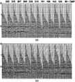
Dipping events are then moved to their supposedly true subsurface positions, and diffractions are collapsed by migrating the stacked section prior to amplitude scaling (migration). Figure 1.5-24 shows the CMP stack as in Figure 1.5-22 after migration. As for the unmigrated stack, the migrated section also is displayed with the scaled amplitudes (Figure 1.5-25). Although the output of migration is intended to represent the geological cross-section along the line traverse, it often is displayed in time as for the input stacked section. The provided lateral velocity variations are mild to moderate, time migration often is acceptable; otherwise, depth migration is imperative (migration).
The structural highs below midpoints 4200, 6800, and 8200 in Figure 1.5-25 are associated with mud diapirism which is prominent in the Caspian basin. Structural complexity caused by faulting and folding generally introduces problems in stacking and imaging the subsurface in three respects:
- Steeply dipping reflections associated with fault planes and salt flanks often conflict during stacking with gently dipping or near-flat reflections associated with the less undisturbed strata. The remedy for this problem is prestack time migration for which the robust alternative is dip-moveout correction combined with poststack time migration.
- Nonhyperbolic moveout caused by strong lateral velocity variations associated with complex overburden structures involving salt tectonics and over-thurst tectonics yields traveltime and amplitude distortions during stacking based on the hyperbolic moveout assumption. The remedy for this problem is prestack depth migration.
- Any of the two cases described in (a) and (b) often manifest themselves as 3-D problems in nature. The remedy for the 3-D effects, of course, is 3-D migration.
The migrated section in Figure 1.5-25 must be evaluated within the above limitations in stacking and imaging the subsurface.
See also
- Preprocessing
- Deconvolution
- CMP sorting
- Velocity analysis
- Normal-moveout correction
- Multiple attenuation
- Dip-moveout correction
- CMP stacking
- Poststack processing
- Residual statics corrections
- Quality control in processing
- Parsimony in processing


