Dip filtering of coherent linear noise
 | |
| Series | Investigations in Geophysics |
|---|---|
| Author | Öz Yilmaz |
| DOI | http://dx.doi.org/10.1190/1.9781560801580 |
| ISBN | ISBN 978-1-56080-094-1 |
| Store | SEG Online Store |
Figure 6.2-5 shows four common-shot gathers, while Figure 6.2-6 shows their f − k spectra before and after f − k dip filtering. The pass or reject zones in the f − k spectra do not need to be constrained to fan shape. The left half of the spectra mostly contain spatially aliased data. By keeping the fan shape in the right quadrant, while zeroing out most of the left quadrant, the coherent noise trains, including the aliased energy, are eliminated.
Because aliasing is a serious concern in f − k filtering, it is advisable to apply it to shot gathers rather than to CMP gathers, since CMP gathers can have twice the trace spacing of shot gathers. Nevertheless, two neighboring CMP gathers can be interleaved before applying f − k dip filtering, then split afterward, thus alleviating aliasing. Such implementation is permissible provided the composite gather does not exhibit any traveltime shifts caused by changes in reflector geometries or lateral variations in velocities. Coherent noise as seen on the shot gathers in Figure 6.2-5 is best attenuated in the shot-gather domain. When sorted into CMP gathers, no significant remnant of this noise is left in the data (Figure 6.2-7). Figure 6.2-8a shows the stacked section derived from the CMP gathers in Figure 6.2-7a with no f − k filtering. Note the linear noise left in the stacked section. The CMP gathers with f − k filtering (Figure 6.2-7b) yield a stack that is virtually free of linear noise (Figure 6.2-8b).
Coherent linear noise on stacked data also can be suppressed by poststack migration that incorporates dip filtering. If coherent linear noise is associated with side scatterers, then much of it can be attenuated by a constant-velocity DMO correction (dip-moveout correction in practice). If f − k filtering were not applied to common-shot gathers containing side-scattered energy, then a stacked section with coherent linear noise could result (Figure 6.2-9a). Figure 6.2-9b shows that this noise can be attenuated by f − k dip filtering the stacked section. Could this noise attenuation be done better? If an f − k filter were applied to shot records, then the stack in Figure 6.2-9c results. When compared to the result in Figure 6.2-9b, the result in Figure 6.2-9c seems to offer better resolution. The prestack f − k filtered data also yield an improved velocity analysis (Figure 6.2-10).
Practical experience with f − k filtering proves that an even better stack may result when both common-shot and common-receiver gathers are f − k filtered. The resulting stack is shown in Figure 6.2-9d. Compare this with stacked sections in Figures 6.2-9b,c. If f − k filtering were done on only the shot gathers, then a good portion of coherent noise may remain in the data. Although this remaining noise may be attenuated by a second pass of f − k filtering on receiver gathers, enhanced smearing of the data can degrade reflector definition.
-
 Figure 6.2-5 Four shallow marine records (a) before and (b) after f − k dip filtering to remove coherent linear noise. The coherent noise seen in these records is primarily of the guided wave type. (Data courtesy Deminex Petroleum.)
 -
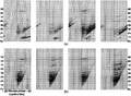 Figure 6.2-6 The f − k spectra of the shot gathers in Figure 6.2-5 (a) before and (b) after f − k dip filtering.
 -
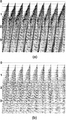 Figure 6.2-7 The CMP gathers from a shallow marine survey (a) before and (b) after f − k dip filtering implemented in the shot-gather domain to remove coherent linear noise. (These are the same data as in Figure 6.2-5.) (Data courtesy Deminex Petroleum.)
 -
 Figure 6.2-8 (a) CMP stack with some coherent linear noise; and (b) f − k dip filtering before stack. Selected CMP gathers are shown in Figure 6.2-7. (Data courtesy Deminex Petroleum.)
 -
 Figure 6.2-9 (a) CMP stack contaminated by coherent noise. Associated common-shot and CMP gathers are shown in Figure 6.0-1. (b) The same CMP stack f − k filtered after stack. (c) CMP stack f − k filtered before stack. (d) CMP stack f − k filtered twice before stack — first, in common-shot domain, second, in common-receiver domain. (Data courtesy Taylor Woodrow Energy Ltd.)
 -
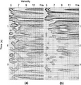 Figure 6.2-10 Velocity spectrum associated with the data in Figure 6.0-1b (a) without and (b) with f − k dip filtering.


See also
- Random noise and frequency-wavenumber filtering
- Statics corrections and frequency-wavenumber filtering
- Frequency-wavenumber multiple attenuation
External links
| find literature about Dip filtering of coherent linear noise |