Wraparound
 | |
| Series | Investigations in Geophysics |
|---|---|
| Author | Öz Yilmaz |
| DOI | http://dx.doi.org/10.1190/1.9781560801580 |
| ISBN | ISBN 978-1-56080-094-1 |
| Store | SEG Online Store |
Wraparound is the effect of finite data length in time and space on a migration algorithm implemented in the Fourier transform domain. A migration algorithm implemented in the time-space domain does not suffer from wraparound effect. But a migration algorithm implemented in the frequency-space domain suffers from wraparound along the time axis. Similarly, a migration algorithm implemented in the frequency-wavenumber domain suffers from wraparound effects both along the time and space axes.
Figure 4.5-22 shows a zero-offset section that contains a diffraction hyperbola and its migration using frequency-wavenumber migration based on the phase-shift method. When plotted with a very high display gain, we observe the energy in the migrated section bouncing off the edges of the section both in the time and space directions.
A field data example of the wraparound effect on frequency-wavenumber migration is shown in Figure 4.5-23. This is the same section as in Figure 4.2-15b, except that it has been displayed using a very high gain. The energy above the water bottom is associated with the wraparound effect in the time and space directions. The wraparound noise actually exists within the image portion of the section, also. A way to reduce the wraparound effect is to pad the data with zeros along the axis of Fourier transformation. For frequency-space migration, data must be padded along the time axis; and for frequency-wavenumber migration, data must be padded along both the time and space axes.
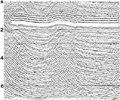
A field data example of the wraparound effect on frequency-space migration is shown in Figure 4.5-24. This is the same section as in Figure 4.4-11d, except that it has been displayed using a very high gain. The energy above the water bottom is associated with the wraparound effect in the time direction.
-
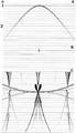 Figure 4.5-22 Wraparound effect in frequency-wavenumber migration: (a) a zero-offset section that contains a diffraction hyperbola with 2500-m/s velocity, (b) desired migration using the phase-shift method, and (c) the same as in (b) but with a display gain that is 100 times greater than that used in (b).
 -
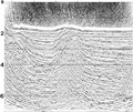 Figure 4.5-23 Wraparound effect in frequency-wavenumber migration: The input stacked section is shown in Figure 4.2-15a and the desired migration using the phase-shift method is shown in Figure 4.2-15b.
 -
 Figure 4.2-15 (a) A CMP-stacked section, and (b) migration using the phase-shift method. Event A is the water-bottom multiple, and Event B is the peg-leg multiple associated with the top-salt boundary. These multiples are respectively denoted by Events C and D on the migrated section.
 -
-
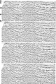 Figure 4.4-11 Tests for extrapolation depth step size in 65-degree frequency-space implicit finite-difference migration using, from top to bottom, 8-ms, 12-ms, 16-ms, and 20-ms depth steps. The input CMP stack is shown in Figure 4.2-15a, and the desired migration using the phase-shift method is shown in Figure 4.2-15b.


See also
External links
| find literature about Wraparound |